|
|
|
|
|
|
Hello John,
Since I last contacted you I have finalized things with the 712. The
following is what I have done:
1.
I use a dynamic microphone/headset arrangement from
Roanwell Headsets.
2.
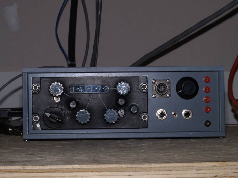
I have made a case for the control panel (714-E3) which I
purchased from Fair Radio as a control panel for an ARC-95 system.
3.
Inside the case I have mounted a 317 three terminal
adjustable regulator to provide 12 volts from the 32 volts which
is supplied via the main cable from the 712.
4.
This regulator powers an 8 pin IC pre-amplifier for the
microphone and a 5 terminal 3 watt amplifier for headphones and speaker.
5.
A provision for PTT is also provided for the headset and a
separate front panel jack for a foot switch.
6.
A TUNE ENABLE miniature switch is mounted on a panel at
the rear (actually the front) of the 712 for tune-up.
7.
From the front panel on the 712 a cable runs to my case
which supplies switching for the main antenna/receive
antenna connectors on the 712. This cable also takes voltages to jacks
on my case so as to enable metering important voltages from the 712.
8.
The original main antenna connector on the 712 has been
changed to a type “N”.
I have today had QSO’s with two of the Route 66 special event stations. Conditions were deplorable and other than the signal being very readable it was too difficult to comment on signal quality. I run about 400 watts PEP with no problems.
The 3 phase 400 Hz. 110 volt supply is a Pacific Power Systems ASX-315 laboratory supply. This is overkill but I obtained it rather inexpensively.
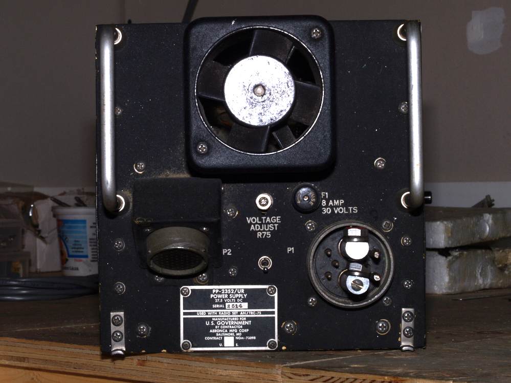
I also have a PP-2352/UR solid state supply (I think made for the ARC-75 system) which is a 2 kilowatt, 3 phase, 400 Hz, 110 volt supply which runs off 28 (24) volts.
OK heres an update Dated Jan 10, 2018
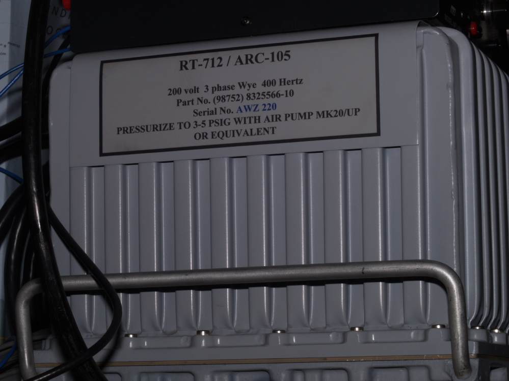
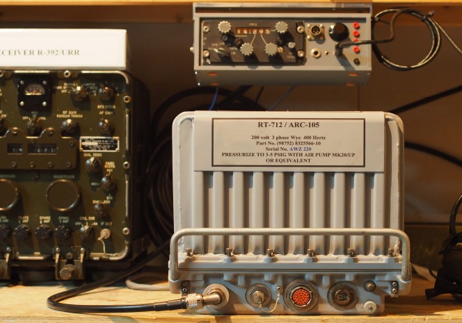
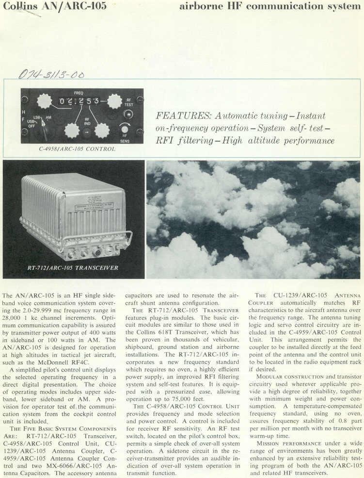
Collins
RT-712
Part of ARC-105 A pressurized communications system especially designed
for
tactical jet aircraft with performance characteristics comparable to the
618-T.
I purchased my RT-712 (712) quite a few years ago and although I used it to receive on from time to time I never seriously set about putting it on the air.
During the period soon after I purchased it I spent much time, money and
effort attempting to provide the three phase, 400 Hertz, 110 volt
power required. Initially I purchased three 110 volt single phase 400
Hertz units which operated from a 28 volt source. Attempting to
maintain the necessary 120 degree phase difference between the three
units proved an impossibility.
Next
I had a 24 volt high current automobile alternator rewound such that it
produced the requisite 110 volt three phase power
when coupled to a 240 volt synchronous electric motor; whilst this was
successful the heat rise over time precluded this method from being
used over a long period of time.
Next
I purchased three military aircraft power supplies, the PP-2352 UR,
which were designed to provide three phase, 400 Hertz,
110 volt power and were used, I believe, in the ARC-58 system which
appears to be a precursor to the ARC-105 system.
These
units however produced only square wave power other than for a one phase
filtered sine wave for use
with low power waveform conscious devices.
Whilst I now had what in the future would be a totally suitable supply
for the 712, I was somewhat loathe
to place its square wave output into my 712 so I hunted further for what I
considered, at that time, something more suitable.
This
I eventually found through a friend who knew of someone who was selling
a Pacific Power Source 315-ASX
programmable power supply capable of more than satisfying my
requirements. This supply is a beautiful thing
and is capable of one, two or three phase output of programmable output
voltages and output frequencies and can
provide up to two kilowatts of power. It is all solid state. Its input
requirements are 120 /240 volts at 50/60 Hertz.
I now set about preparing the 712 for airtime operation.
When
I initially acquired the 712 I purchased a second one as spares plus a
separate power supply module and
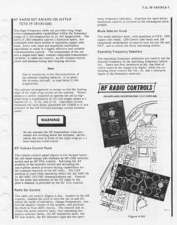
at that time I purchased a 714-E3 cockpit control unit which, whilst not
designed specifically for the 712,
works perfectly without any modification whatsoever (contrary to what
some would have you believe).
It should further be noted that some modules are interchangeable between
the 712 and the 618T series,
again contrary to what some claim.
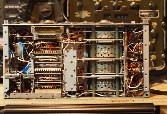
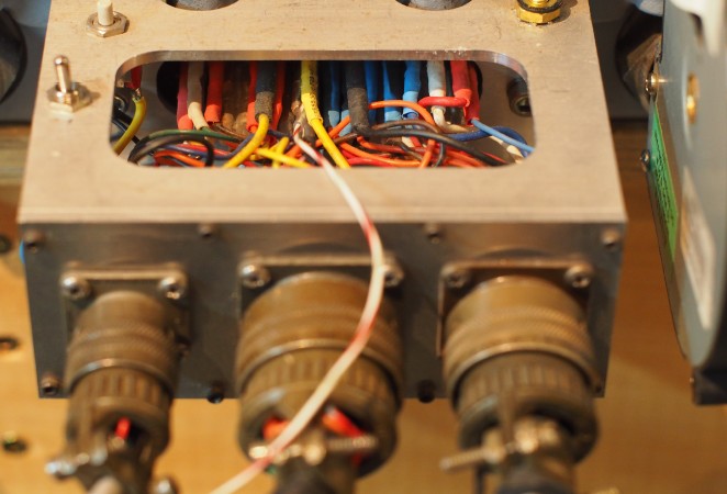
The
female connector which formed part of the original rack mount was
impossible to obtain thus some other means
needed to be found to connect the 712 mounted male to external devices
such as the control head, power supply and audio systems.
To
this end I purchased a multitude of Amphenol 18-12S connectors which I
could purchase without the shell.
Thus I had enough female pins, of the correct size, to place over the
male pins in the ITT Cannon connector on the 712.
These female pins are perfect for the job.
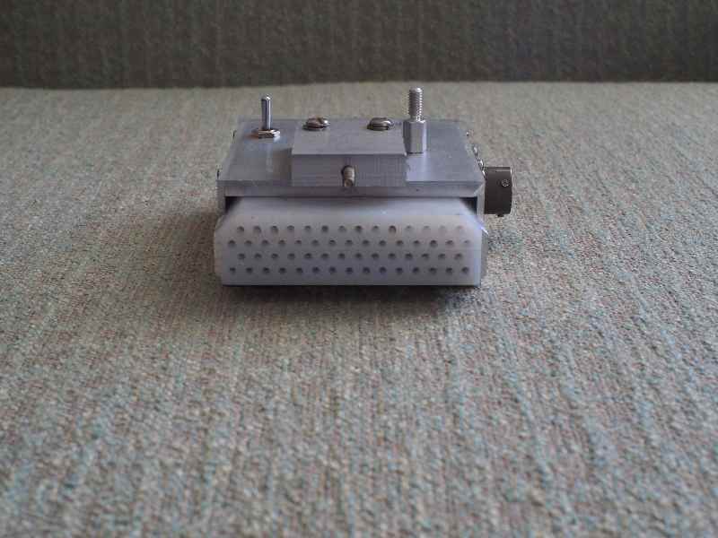
The
connector needed to mate with the connector at the rear of the Control
Head is an Amphenol PT06A20-30S(SR)
and is readilly available from various suppliers.
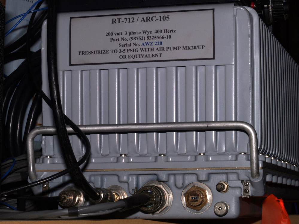
For
the three phase power to the 712 I used Amphenol PT06A14-5S(SR)
connectors, male mounted on the rear
of the 712 and female to the Pacific Power Systems unit. For mic,
speaker and PTT connections I used a Cannon 6 pin
connector and mate but anything suitable could have been used.
Although my installation is now such that the control head and the 712
are within a few feet of each other I had originally
envisaged a much greater distance separating the units thus my cabling
is much longer than necessary.
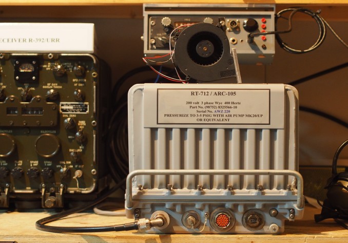
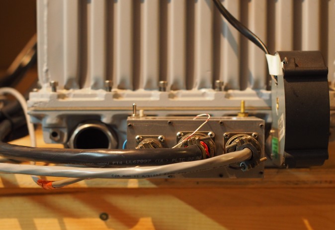
The
pressurized system requires that cooling air be passed through the unit
so as to remove the warmed internal air.
To this end I used a surplus Sony fan model No. SFF22C. Attached
pictures show the fan but as is obvious any suitable alternative could
be used.
I was
unable to purchase schematics for the RT-712 but was able to, for an
outrageous price, purchase copies of the 618-T1 manual
which references the ARC-105 and has the schematics necessary for
maintenance and wiring of and for the 712. I am led to
believe that more up to date data is available from KŘIP at a very
reasonable price. I paid USD250 for my manual and I
think that KŘIP (pocatelloarc.org/618t) gets a $5 donation.
I then set about fabricating the housing for the control head and mic and speaker controls, sockets etc.
Within my control module I have placed a 12 volt three terminal
regulator (supplied by a 32 volt source
coming in to the connector on the control head), a five watt audio
amplifier integrated circuit and an LM380
preamp integrated circuit for the dynamic microphone which I use. This
microphone by the way is part of a
Roanwell military headset and the insert has a response which is flat
from 600 to 3000 Hertz. All reports that
I have received note than the audio quality is excellent.
When
the unit is powered up and completely enclosed in its housing very
little noise emanates from it, this
however is in stark contrast to the fan noise generated when the finned
cover is removed. This little fan turns
at 20,000 RPM and although small is very noisy. The fan from the PP-2352
is also very noisy.
My
unit puts out a very comfortable 300 watts PEP and is really just idling
along. I could turn the mic gain up
but things are fine at the 300 watt level. On AM 100 watts carrier is
the norm. I am not a CW person so have
never used it on CW although provision is there for this option. Both
upper and lower sideband are supported.
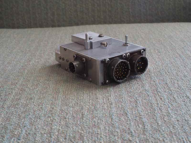
Initially I completely stripped the unit from its chassis and sand
blasted and painted the base and case and at that
time I replaced the main antenna connector with an “N” type. This was
accomplished by fabricating a circular
fitting drilled such that the type “N” mounted in it and I attached it
to the 712 lower case via three machine screws.
On
the front of the unit are two antenna connectors, the type “N” mentioned
earlier and a “BNC” connector which
can be used in installations where a separate receive antenna is
desired. This connection is enabled by connecting to
ground, pins of either the unit front connector (16-26P) or the main
rear connector.
Further to this is that all important voltages can be monitored via the
front 16-26P connector. I found the mate
to this connector a PT026A16-26P(SR) difficult to obtain but did
eventually manage to find one.
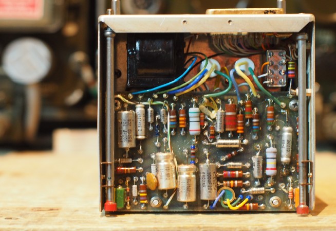
There
were two more “modifications” which I performed. The first was the
change from 100 microfarads “AGC Capacitor”
in the AM module to 4.7 microfarads as the AGC release rate was too slow
(for me) and the grounding at the “Sidetone”
potentiometer of the “Audio Cold” point. Neither of these modifications
were vitally necessary but for me they made sense.
Finally, this is a beautiful unit, very typical of Collins and rock
solid in stability. I find it a joy to operate and my only wish
is that I was able to tune to the half KC points, but that is a very
small complaint and it is far outweighed by everything else about the
machine.
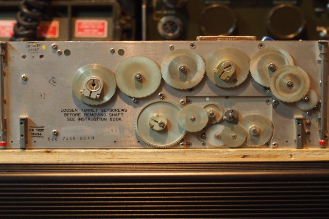
Pictures are attached so as to show how I solved various mechanical issues.
Phillip Grimison VE6ABW
Langdon Alberta Canada e-mail:
phillip.grimison@yahoo.com
 |
 |
 |
 |
 |
 |
 |
 |
 |
|
Here's an interesting site, about the ARC-105
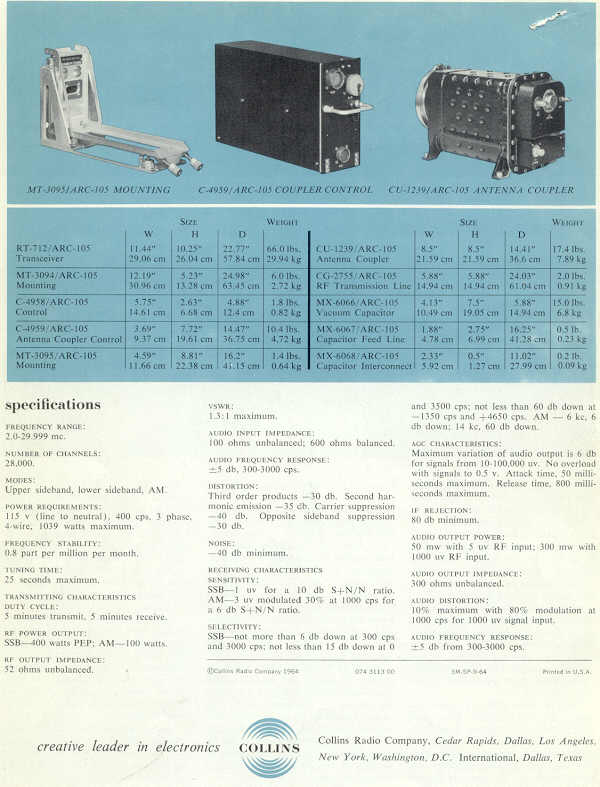
CHARACTERISTICS
Technical Specifications:
Frequency Range: 2.0 – 29.999 Mhz.
Power Source: 208 volts, 400 Hertz, 3 phase. (208 volts, Wye connected, 3 phase with grounded neutral
Power Requirements: Receive – 180 watts. Transmit SSB – 800 watts. Transmit AM – 1050 watts
Frequency Stability: Less than one part per million per month
Channel Change Time (nominal): Eight second
Ambient Temperature Range: Negative 40 degrees celsius to positive 50 degrees celsius
Ambient Humidity Range: Up to 90% humidity at 50 degrees celsius for 48 hours
ltitude Range: Pressure equivalent of 75,000 feet
Transmitting Characteristics:
RF Power Output: SSB – 400 watts PEP. AM – 100 watts carrier
RF Output Impedance:52 ohms
VSWR: Transmitter shall provide specified output into a 52 ohm load with SWR not exceeding 1.3:1
Audio Frequency Response: 5 dbs. Peak to valley ratio from 300 – 3000 Hertz
Distortion: SSB – third order products down at least 30 dbs. AM – less than 20% at 85% modulation
Receiver Characteristics:
Sensitivity: SSB – 1 microvolt for a 10 dbs. S+S/N ratio. AM – 3 microvolts modulated 30% at 1000 Hertz for a 6 dbs. S+S/N ratio
Selectivity:
SSB – 2.85 Khz. - 6 dbs. Down. 6 KhZ. - 40 dbs. down
AM – 5.5 Khz. - 6 dbs. Down; 14 Khz. - 60 dbs. Down
AGC Characteristics: Minimum variation of audio output is 6 dbs. For signals from 10 – 100,000 microvolts
IF Rejection: 80 dbs. Minimum
Audio Power Output 100 mw into a 300 ohm load
Audio Distortion: Less than 10%
Audio Frequency Response: 5 dbs. Peak to Valley ratio from 300 – 3000 Hertz